The previous suite of tests, based on ASHRAE Standard 140-2007, verifies that the simulation engine produces results that are reasonable. Each test requires a simulation to be run. The tests in this section are intended to verify that the software correctly constructs the proposed design and baseline buildings and correctly applies the proposed design input restrictions specified in Chapter 6 and Appendix A.
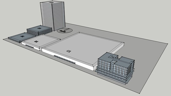
The simulations described in this section use five prototype buildings. Prototypes A1, A3 and A20 are all the same five-zone, 150 ft x 150 ft, floor plate, but with one, three and 20 stories. Prototypes B1 and C1 are five-zone, one-story, square prototype buildings measuring 200 ft x 200 ft and 400 ft x 400 ft respectively. Prototype D is a more complex, mixed use building with a below-grade garage, retail on the first level, office space on levels two and three, and four stories of multi-family housing over the office. Figure 1 is an image of all of the prototype buildings, positioned next to each other. Appendix E has a SketchUp file with the detailed geometry for each of the prototypes. Appendix E also has a spreadsheet with tabular detail on each of the prototype buildings along with forms for the software vendor to complete.

Figure 2-1: Prototype Buildings for Software Tests
Evaluation of the modeling assumptions and baseline building tests is qualitative. The software developer shall use the candidate software and make the simulations described in this section for the proposed design and the baseline building. The input and output files for each of these cases shall then be evaluated by the software developer to verify that:
- Default schedules of operation are applied for both the baseline building and the proposed design.
- The baseline building use the correct system types as prescribed in Chapter 6.
- An economizer (of the right type) is included in the baseline building if required.
- The primary and secondary baseline building systems are properly specified and sized.
- Fan brake horsepower is correctly specified for the baseline building.
- The baseline building is correctly rotated and the equipment is re-sized for each rotation.
- The baseline building envelope constructions are correctly substituted for exterior opaque surfaces, partitions and fenestration.
- Fenestration area in the baseline building is reduced, when the proposed design fenestration area is greater than the limit.
- The baseline building lighting system is correctly specified and that exterior lighting is modeled.
- Receptacle loads, refrigeration equipment and other equipment is modeled according to the rules in this manual.
- Prescribed modeling assumptions are applied for both the baseline building and the proposed design.
- Elevators in Prototypes A20 and D are included.
- Overhangs are modeled in the proposed design for Prototype D but not the baseline building.
- The models make a reasonable estimate of unmet load hours.
- Unconditioned spaces are modeled.
- Other baseline building specifications and/or modeling assumptions are correctly applied.
As the software developer verifies the above and other conditions, the input and output files should be annotated with comments (or by some other means) to demonstrate that the modeling rules are correctly applied. Software developers should use the output format spreadsheets, included in Appendix E, to report the results of these tests. These annotated files are then submitted to COMNET for further evaluation. Any errors discovered shall be corrected by making modifications to the software; the simulations shall be repeated; and the new results shall be annotated for submittal to COMNET.
