This group of building descriptors is applicable for spaces that have daylighting controls.
| Daylight Modeling Method | |
| Applicability | All spaces with daylighting controls |
|---|---|
| Definition |
The method used to model daylighting. Daylighting credits must be calculated based on the local climate and daylight models of the space. Building descriptors are provided in this section for an internal daylighting model and two variations of an external daylighting model:
|
| Units | List (see above) |
| Input Restrictions | As designed |
| Baseline Rules | Not applicable |
| Lighting Schedules for Daylighting | |
| Applicability | Daylighted spaces that use the schedule adjustment method |
|---|---|
| Definition | A schedule that indicates the reduction in electric lighting for the lighting system that is being controlled. This schedule is applied to the lighting schedule (see above) to produce a schedule for lighting with daylighting controls. |
| Units | Data structure: schedule, fractional |
| Input Restrictions | The schedule of adjustments should account for seasonal variations in the time of day. Since the schedule will apply for both sunny days and overcast days, the adjustments should represent the conservative condition, e.g. the smallest savings. |
| Baseline Rules | Baseline does not have daylighting |
| Daylight Ratios | |
| Applicability | Daylighted spaces that use the daylight ratio method |
|---|---|
| Definition | A matrix of daylight factors for the space that represent the ratio on illumination at the daylighting reference point to the exterior illumination. The simulation engine calculates the daylighting illumination at the reference point based on this information and the exterior illumination and uses the daylighting control building descriptors to determine for each hour how the lighting power is reduced. |
| Units | Data structure: matrix |
| Input Restrictions | The special daylighting program used to calculate the daylight factors should use inputs consistent with those described below for the internal daylight model method. |
| Baseline Rules | The baseline building does not have daylighting |
| Daylighted Area | |
| Applicability | All daylighted spaces |
|---|---|
| Definition | The floor area that is daylighted. Two types of daylighted areas are recognized. The primary daylighted area is the portion that is closest to the daylighting source and receives the most illumination. The secondary daylighted area is an area farther from the daylighting source, but still receives useful daylight. |
| Units | Data structure |
| Input Restrictions |
The default primary daylight area for sidelighting is a band near the window with a depth equal to the distance from the floor to the top of the window. The default secondary daylight area for sidelighting is a band beyond the primary daylighted area that extends a distance double the distance from the floor to the top of the window. Other daylight areas may be defined with appropriate documentation. The default primary daylight area for toplighting is a band around the skylight well that has a depth equal to the 70% of the ceiling height. The default secondary daylight area for toplighting is a band beyond the primary daylighted area that extends 140% of the ceiling height. Daylighted areas may not overlap or extend beyond partitions higher than 5 ft. Error checking includes ensuring that the following is true: Sidelit depth is less than or equal to ceiling height. Total daylit area is no greater than space area. |
| Baseline Rules | The baseline building does not have daylighting |
| Reference Position for Illuminance Calculations | |
| Applicability | Daylighted spaces that use the internal daylight model method |
|---|---|
| Definition | The position of the daylight reference point within the daylighted space. Lighting controls are simulated so that the illuminance at the reference position is always above the illuminance setpoint. Thus for step switching controls, the combined daylight illuminance plus uncontrolled electric light illuminance at the reference position must be greater than the setpoint illuminance before the controlled stage of lighting can be tuned off. Similarly, dimming controls will be dimmed so that the combination of the daylight illuminance plus the controlled lighting illuminance is equal to the setpoint illuminance. |
| Units | Data structure |
| Input Restrictions | The reference location shall be as far away from daylight apertures as possible (but still within the daylighted area) so that all occupants have sufficient amounts of total illuminance (combined daylight and electric light) under all daylighting conditions. |
| Baseline Rules | The baseline building does not have daylighting. |
| Illuminance Setpoint | |
| Applicability | Daylighted spaces that use the internal daylight model method |
|---|---|
| Definition | The design illuminance for the daylighted space. The daylighting control adjusts the controlled lighting to maintain this level of illuminance at the reference point. |
| Units | Footcandles |
| Input Restrictions | As designed, but should be consistent with the visual tasks in the space and the recommendations of the IESNA. |
| Baseline Rules | Baseline does not have a daylighting control. |
| Fraction of Controlled Lighting | |
| Applicability | Daylighted spaces that use the internal daylight model method or the daylight ratio method |
|---|---|
| Definition | The fraction of the lighting power in the daylighted space that is controlled by daylight. This is applicable when some of the luminaires in the space are controlled by daylighting and others are not. This input can be eliminated if multiple lighting systems are modeled for each space and the system that is controlled by daylight is separately specified. |
| Units | Numeric: fraction |
| Input Restrictions | As designed |
| Baseline Rules | Baseline does not have a daylighting control. |
| Daylighting Control Type | |
| Applicability | Daylighted spaces that use the internal daylight model method or the daylight ratio method |
|---|---|
| Definition |
The type of control that is used to control the electric lighting in response to daylight available at the reference point. The options are:
[figure title="Example Stepped Daylighting Control" id="example-stepped-daylighting-control"] [figure title="Example Dimming Daylight Control" id="example-dimming-daylight-control"] |
| Units | List (see above) |
| Input Restrictions | As designed |
| Baseline Rules | Baseline does not have a daylighting control. |
 [/figure]
 [/figure]
| Minimum Dimming Power Fraction | |
| Applicability | Daylighted spaces that use the internal daylight model method or the daylight ratio method and dimming controls |
|---|---|
| Definition | The minimum power fraction when controlled lighting is fully dimmed. Minimum power fraction = (Minimum power) / (Full rated power). See [bookref id="example-dimming-daylight-control"]. |
| Units | Numeric: fraction |
| Input Restrictions | As designed |
| Baseline Rules | Baseline does not have a daylighting control. |
| Minimum Dimming Light Fraction | |
| Applicability | Daylighted spaces that use the internal daylight model method or the daylight ratio method and dimming controls |
|---|---|
| Definition | Minimum light output of controlled lighting when fully dimmed. Minimum light fraction = (Minimum light output) / (Rated light output). See [bookref id="example-dimming-daylight-control"]. |
| Units | Numeric: fraction |
| Input Restrictions | As designed |
| Baseline Rules | Baseline does not have a daylighting control. |
| Number of Control Steps | |
| Applicability | Daylighted spaces that use the internal daylight model method or the daylight ratio method and stepped controls |
|---|---|
| Definition | Number of control steps. For step switching, this term defines even steps of light output and even steps of rated power fractions. For step dimming, identifies number of steps that require fraction of rated light output and rated power fraction. |
| Units | Numeric: integer |
| Input Restrictions | Integer less than 10. |
| Baseline Rules | Baseline does not have a daylighting control. |
| Step Dimming Control Points | |
| Applicability | Daylighted spaces that use the internal daylight model method or the daylight ratio method and stepped dimming controls |
|---|---|
| Definition | Number of control steps. For step switching, this term defines even steps of light output and even steps of rated power fractions. For step dimming, identifies number of steps that require fraction of rated light output and rated power fraction. |
| Units | Data structure. Matched pairs of data (light output and fraction of rated power) for the defined number of control steps |
| Input Restrictions | Integer less than 10. More than 10 steps approximate with continuous dimming. |
| Baseline Rules | Baseline does not have a daylighting control. |
This group of building descriptors is applicable for spaces that have daylighting controls.
General Daylighting Requirements for Toplighting
ASHRAE Standard 90.1-2010 requires that spaces have skylights and be daylighted when the space is:
1) Greater than 5,000 ft²,
2) Located directly under a roof,
3) With a ceiling height greater than 15 ft, and
4) One of the following space types: office, lobby, atrium, concourse, corridor, non-refrigerated warehouse or storage, gymnasium/exercise center, convention center, automotive service, manufacturing, retail, distribution/sorting area, transportation, or workshop.
5) Located in thermal zones 1 through 5,
6) Has an allowed interior lighting power density of 0.5 W/ft² or greater, and
7) Not substantially shaded (see the text below on what qualifies). Substantial shading occurs when 90% of the qualifying space roof area is shaded at noon on the summer solstice.
COMNET accredited software shall have the capability to identify these conditions and model daylighting in the baseline building when they all occur. When required, the baseline building daylighting system shall be defined as follows:
1) The qualifying space in the baseline building shall have the same physical dimensions and configuration as the rated building. The qualifying space is the entire space, half of which is required to be daylighted.
2) The qualifying space shall be divided into two equal parts with one part daylighted and the other part not daylighted. For rectangular spaces , the longer dimension shall be bisected creating two equally dimensioned spaces.
3) The daylighted space (half of the qualifying space) shall have skylights with sizes and spacing defined as follows. These rules result in a skylight area that is equal to approximately 3% of the daylighted area.
a) Square skylights shall have a dimension on each side of 0.3 times the ceiling height. There shall be no skylight well.
b) Skylights shall be spaced in both directions at a distance of 1.7 times the ceiling height thereby creating a continuous daylighted area in both directions.
c) The skylight grid defined above shall be centered in the daylighted portion of the qualifying space such that the edge of skylights are no further than 0.7 times the ceiling height from the edges of the daylighted portion.
4) The skylights shall have a visible transmittance of 40%. The U-factor and SHGC shall be equal to the prescriptive requirements for plastic skylights on a curb for the applicable climate zone and building classification (nonresidential, residential or semi-heated).
5) The illuminance setpoint shall be:
a) 40 footcandles for lobby, atrium, concourse, corridor, gymnasium/exercise center, convention center, automotive service, manufacturing, and retail.
b) 15 footcandles for non-refrigerated warehouse or storage, gymnasium/exercise center, and distribution/sorting area, transportation, or workshop.
6) The daylighting reference point shall be positioned in the center of the daylighted space.
7) The electric lighting system shall be automatically controlled by step switching in response to available daylight with the first control step at 67% of design lighting power and the second control step at 33% of design power.
a) Daylighting Control Type = Step Switching
b) Number of Control Steps = Three (100%, 67% and 33%)
8) The electric lighting controls shall capable of being easily and accurately calibrated . In particular:
a) The light sensor shall be remote from where calibration adjustments are made, and
b) The calibration adjustments shall be readily accessible.
General Daylighting Requirements for Sidelighting
ASHRAE Standard 90.1-2010 requires that primary sidelighted areas have automatic daylighting controls. Primary sidelighted areas that require such controls are defined as follows:
1) The depth of the primary sidelighted area is equal to the window head height, where the window head height is the distance from the floor to the top of the window.
2) The width of the primary sidelighted area is the width of the window plus 2 ft on each side.
3) The area of the primary sidelighted area in an enclosed space is equal to or greater than 250 ft². The area is the depth of the primary sidelighted area times the combined width.
4) The windows creating the primary sidelighted area have an effective aperture of 0.1 or greater. The effective aperture is the product of the window wall ratio and the visible transmission of the window divided by the primary sidelighted area.
5) The windows creating the primary sidelighted area are not significantly shaded. Significant shading is deemed to occur when structures exist that have a profile angle of 45 degrees or greater. The profile angle is the angle between the horizon and a line from the top of the window to the top of adjacent structures.
COMNET accredited software shall have the capability to identify these conditions and model daylighting controls in the baseline building when they all conditions occur. When required, the baseline building daylighting system shall have the following characteristics:
1) The physical configuration of the enclosed space and the windows that create the primary sidelighted area shall be the same as the rated building, following the rules of Section 6.5.7.
2) The windows shall have a U-factor, SHGC and VT equal to the prescriptive requirements for the applicable climate zone and building classification (nonresidential, residential or semi-heated).
3) The illuminance setpoint shall be:
a) 40 footcandles for lobby, atrium, concourse, corridor, gymnasium/exercise center, convention center, automotive service, manufacturing, and retail.
b) 15 footcandles for non-refrigerated warehouse or storage, gymnasium/exercise center, and distribution/sorting area, transportation, or workshop.
4) The daylighting reference point shall be positioned mid distance in the width of the space and located two thirds of the way to the back of the daylighted space.
5) The electric lighting system shall be automatically controlled by step switching in response to available daylight with the first control step at 67% of design lighting power and the second control step at 33% of design power
a) Daylighting Control Type = Step Switching
b) Number of Control Steps = Three (100%, 67% and 33%)
6) The electric lighting controls shall capable of being easily and accurately calibrated. In particular:
a) The light sensor shall be remote from where calibration adjustments are made, and
b) The calibration adjustments shall be readily accessible.
| Daylight Modeling Method | |
| Applicability | All spaces with daylighting controls |
|---|---|
| Definition |
The method used to model daylighting. Daylighting credits must be calculated based on the local climate and daylight models of the space. Building descriptors are provided in this section for an internal daylighting model and two variations of an external daylighting model:
|
| Units | List (see above) |
| Input Restrictions | As designed |
| Baseline Rules | When the baseline building is required to have daylight controls, the baseline building shall use the same daylighting method as the rated building. If the rated building does not have daylighting, then an internal daylighting model shall be used for the baseline building. |
| Lighting Schedules for Daylighting | |
| Applicability | Daylighted spaces that use the schedule adjustment method |
|---|---|
| Definition | A schedule that indicates the reduction in electric lighting for the lighting system that is being controlled. This schedule is applied to the lighting schedule (see above) to produce a schedule for lighting with daylighting controls. |
| Units | Data structure: schedule, fractional |
| Input Restrictions | The schedule of adjustments should account for seasonal variations in the time of day. Since the schedule will apply for both sunny days and overcast days, the adjustments should represent the conservative condition, e.g. the smallest savings. |
| Baseline Rules | This is applicable when the baseline building is required to have daylilghting (see general requirements above) and when the rated building also has daylighting and uses the schedule adjustment method. In these cases, a daylight schedule is also developed for the baseline building using procedures identical to those used for the rated building. |
| Daylight Ratios | |
| Applicability | Daylighted spaces that use the daylight ratio method |
|---|---|
| Definition | A matrix of daylight factors for the space that represent the ratio on illumination at the daylighting reference point to the exterior illumination. The simulation engine calculates the daylighting illumination at the reference point based on this information and the exterior illumination and uses the daylighting control building descriptors to determine for each hour how the lighting power is reduced. |
| Units | Data structure: matrix |
| Input Restrictions | The special daylighting program used to calculate the daylight factors should use inputs consistent with those described below for the internal daylight model method. |
| Baseline Rules | This is applicable when the baseline building is required to have daylilghting (see general requirements above) and when the rated building also has daylighting and uses the daylight ratio method. In these cases, a (set of) daylight ratio is also developed for the baseline building using procedures identical to those used for the rated building. |
| Daylighted Area | |
| Applicability | All daylighted spaces |
|---|---|
| Definition | The floor area that is daylighted. Two types of daylighted areas are recognized. The primary daylighted area is the portion that is closest to the daylighting source and receives the most illumination. The secondary daylighted area is an area farther from the daylighting source, but still receives useful daylight. |
| Units | Data structure |
| Input Restrictions |
The default primary daylight area for sidelighting is a band near the window with a depth equal to the distance from the floor to the top of the window. The default secondary daylight area for sidelighting is a band beyond the primary daylighted area that extends a distance double the distance from the floor to the top of the window. Other daylight areas may be defined with appropriate documentation. The default primary daylight area for toplighting is a band around the skylight well that has a depth equal to the 70% of the ceiling height. The default secondary daylight area for toplighting is a band beyond the primary daylighted area that extends 140% of the ceiling height. Daylighted areas may not overlap or extend beyond partitions higher than 5 ft. Error checking includes ensuring that the following is true: Sidelit depth is less than or equal to ceiling height. Total daylit area is no greater than space area. |
| Baseline Rules | Defaults shall be used to define the daylighted area for the baseline building, both under skylights and primary sidelighted area. |
| Reference Position for Illuminance Calculations | |
| Applicability | Daylighted spaces that use the internal daylight model method |
|---|---|
| Definition | The position of the daylight reference point within the daylighted space. Lighting controls are simulated so that the illuminance at the reference position is always above the illuminance setpoint. Thus for step switching controls, the combined daylight illuminance plus uncontrolled electric light illuminance at the reference position must be greater than the setpoint illuminance before the controlled stage of lighting can be tuned off. Similarly, dimming controls will be dimmed so that the combination of the daylight illuminance plus the controlled lighting illuminance is equal to the setpoint illuminance. |
| Units | Data structure |
| Input Restrictions | The reference location shall be as far away from daylight apertures as possible (but still within the daylighted area) so that all occupants have sufficient amounts of total illuminance (combined daylight and electric light) under all daylighting conditions. |
| Baseline Rules | This is applicable to the baseline building when the baseline building has daylighting and the internal daylight model method is used (see rules above). In these cases, the reference position shall be in the center of toplighted spaces. For primary sidelighted areas, the reference position shall be in the center of the width and located two thirds of the way toward the back of the daylighted space (away from the window). |
| Illuminance Setpoint | |
| Applicability | Daylighted spaces that use the internal daylight model method |
|---|---|
| Definition | The design illuminance for the daylighted space. The daylighting control adjusts the controlled lighting to maintain this level of illuminance at the reference point. |
| Units | Footcandles |
| Input Restrictions | As designed, but should be consistent with the visual tasks in the space and the recommendations of the IESNA. |
| Baseline Rules | The illuminance setpoint shall be 40 footcandles for lobby, atrium, concourse, corridor, gymnasium/exercise center, convention center, automotive service, manufacturing, and retail; and 15 footcandles for non-refrigerated warehouse or storage, gymnasium/exercise center, and distribution/sorting area, transportation, or workshop. |
| Fraction of Controlled Lighting | |
| Applicability | Daylighted spaces that use the internal daylight model method or the daylight ratio method |
|---|---|
| Definition | The fraction of the lighting power in the daylighted space that is controlled by daylight. This is applicable when some of the luminaires in the space are controlled by daylighting and others are not. This input can be eliminated if multiple lighting systems are modeled for each space and the system that is controlled by daylight is separately specified. |
| Units | Numeric: fraction |
| Input Restrictions | As designed |
| Baseline Rules | For the baseline building, the daylighted areas are separated, therefore, all lighting in the daylighted areas of the baseline building shall be controlled. |
| Daylighting Control Type | |
| Applicability | Daylighted spaces that use the internal daylight model method or the daylight ratio method |
|---|---|
| Definition |
The type of control that is used to control the electric lighting in response to daylight available at the reference point. The options are:
Figure 6.4.4-1: Example Stepped Daylighting Control
Figure 6.4.4-2: Example Dimming Daylight Control |
| Units | List (see above) |
| Input Restrictions | As designed |
| Baseline Rules | When the baseline building requires daylighting, stepped switching control shall be used. |


| Minimum Dimming Power Fraction | |
| Applicability | Daylighted spaces that use the internal daylight model method or the daylight ratio method and dimming controls |
|---|---|
| Definition | The minimum power fraction when controlled lighting is fully dimmed. Minimum power fraction = (Minimum power) / (Full rated power). See Figure 6.4.4-2. |
| Units | Numeric: fraction |
| Input Restrictions | As designed |
| Baseline Rules | Not applicable when the baseline building is required to have daylighting since stepped controls are used. |
| Minimum Dimming Light Fraction | |
| Applicability | Daylighted spaces that use the internal daylight model method or the daylight ratio method and dimming controls |
|---|---|
| Definition | Minimum light output of controlled lighting when fully dimmed. Minimum light fraction = (Minimum light output) / (Rated light output). See Figure 6.4.4-2. |
| Units | Numeric: fraction |
| Input Restrictions | As designed |
| Baseline Rules | Not applicable when the baseline building is required to have daylighting since stepped controls are used. |
| Number of Control Steps | |
| Applicability | Daylighted spaces that use the internal daylight model method or the daylight ratio method and stepped controls |
|---|---|
| Definition | Number of control steps. For step switching, this term defines even steps of light output and even steps of rated power fractions. For step dimming, identifies number of steps that require fraction of rated light output and rated power fraction. |
| Units | Numeric: integer |
| Input Restrictions | Integer less than 10. |
| Baseline Rules | When the baseline building is required to have daylighting, three control steps shall be used: 100%, 67% and 33% of maximum lighting power. |
| Step Dimming Control Points | |
| Applicability | Daylighted spaces that use the internal daylight model method or the daylight ratio method and stepped dimming controls |
|---|---|
| Definition | Number of control steps. For step switching, this term defines even steps of light output and even steps of rated power fractions. For step dimming, identifies number of steps that require fraction of rated light output and rated power fraction. |
| Units | Data structure. Matched pairs of data (light output and fraction of rated power) for the defined number of control steps |
| Input Restrictions | Integer less than 10. More than 10 steps approximate with continuous dimming. |
| Baseline Rules | Not applicable when the baseline building is required to have daylighting since stepped controls are used. |
This group of building descriptors is applicable for spaces that have daylighting controls.
|
Daylight Modeling Method |
|
|---|---|
|
Applicability |
All spaces with daylighting controls |
|
Definition |
The method used to model daylighting. Building descriptors are provided in this section for an internal daylighting model, two variations of an external daylighting model, and a simplified approach based on power adjustment factors (PAFs): 1.Internal daylighting model. With this method, the simulation model has the capability to model the daylighting contribution for each hour of the simulation and make an adjustment to the lighting power for each hour, taking into account factors such as daylighting availability, geometry of the space, daylighting aperture, control type and the lighting system. The assumption is that the geometry of the space, the reflectance of surfaces, the size and configuration of the daylight apertures, and the light transmission of the glazing are taken from other building descriptors. 2.External daylighting model. An external daylighting model may be used in combination with an hourly simulation program to calculate daylighting savings as long as it produces consistent results and makes use of the key assumptions described below for internal daylighting models. Exterior daylight models include, but are not limited to, the following types of methods: A.Schedule adjustments. With this method, a space is modeled in a stand alone daylighting program to determine the amount of interior daylight available different times of the year and for different times of the day. In addition this program has an electric lighting model that calculates the electricity savings by hour based on interior illuminance and the daylighting control type (switching, dimming etc.). These savings values are converted into a schedule of electric lighting power reduction multipliers. This lighting power reduction schedule is applied to the proposed design energy simulation model and results in reduced electric lighting energy consumption and reduced internal heat gain, both of which are reflected in the proposed design energy consumption. B.Daylight ratio. With this method, an outside program pre-calculates a relationship between outdoor daylight conditions (illuminances or luminances) and interior illuminance. Within the rating software, interior illuminance is calculated from the daylighting ratios and the daylight conditions derived from data on the local weather file. The remainder of the calculations are the same as for an internally calculated daylight model where the interior illuminances are compared to an illuminance setpoint and electric lighting power is calculated based on control type. The two most widely used methods of pre-calculating daylighting ratios are the modified daylight factor method and the daylight coefficients method. a.The modified daylight factor method uses pre-calculated diffuse and direct illuminance daylight factors and multiplies these by diffuse and direct beam outdoor illuminance from the weather file to calculate interior illuminance.1 Daylight factors are calculated from a simulation of the space that relies on user entered information about the space modeled such as orientation, geometry, material properties (transmittances and reflectances) etc. For any given hour, the interior illuminance at the reference point is calculated by the direct beam angle specific daylight factor multiplied by the outdoor direct beam and clear sky illuminance and this is added to the overcast daylight factor multiplied by the overcast sky illuminance. Outdoor direct beam, clear sky and overcast sky illuminances are calculated from the weather data used in the proposed building energy simulation. b.The daylight coefficients method is essentially a similar but more accurate method that relates internal illuminance to the luminance of patches of the sky.2 The sky is divided up into patches as defined by altitude and azimuth. The daylight coefficients are ratios of interior illuminance to luminance for patches or areas on the sky dome. An outside daylight simulation program uses information about the space modeled: its orientation, geometry, material properties (transmittances and reflectances) etc, and calculates daylight coefficients for each sky patch. The precalculated daylight coefficients are then used to calculate interior illuminances for each hour. The illuminance for a location with the space at any point in time is the product of the luminance for each sky patch multiplied by the specific daylight coefficient for each sky patch integrated over the entire sky dome. The luminance for each sky patch is calculated from the weather data used in the proposed building energy simulation. 3.Power adjustment factors. With this method, the lighting power in qualifying daylighted zones may be reduced using power adjustment factors (PAFs). The procedure is similar to how PAFs are applied for occupant sensors and timeclocks. |
|
Units |
List (see above) |
|
Input Restrictions |
As designed |
|
Baseline Rules |
The baseline building has no daylight controls. |
|
Lighting Schedules for Daylighting |
|
|---|---|
|
Applicability |
Daylighted spaces that use the schedule adjustment method to model daylighting |
|
Definition |
A schedule that indicates the reduction in electric lighting for the lighting system that is being controlled. This schedule is applied to the lighting schedule (see above) to produce a schedule for lighting with daylighting controls. |
|
Units |
Data structure: schedule, fractional |
|
Input Restrictions |
The schedule of adjustments should account for seasonal variations in the time of day. Since the schedule will apply for both sunny days and overcast days, the adjustments should represent the conservative condition, e.g. the smallest savings. |
|
Baseline Rules |
This is applicable when the baseline building is required to have daylilghting (see general requirements above) and when the rated building also has daylighting and uses the schedule adjustment method. In these cases, a daylight schedule is also developed for the baseline building using procedures identical to those used for the rated building. |
|
Daylight Ratios |
|
|---|---|
|
Applicability |
Daylighted spaces that use the daylight ratio method |
|
Definition |
A matrix of daylight factors for the space that represent the ratio on illumination at the daylighting reference point to the exterior illumination. The simulation engine calculates the daylighting illumination at the reference point based on this information and the exterior illumination and uses the daylighting control building descriptors to determine for each hour how the lighting power is reduced. |
|
Units |
Data structure: matrix |
|
Input Restrictions |
The special daylighting program used to calculate the daylight factors should use inputs consistent with those described below for the internal daylight model method. |
|
Baseline Rules |
This is applicable when the baseline building is required to have daylilghting (see general requirements above) and when the rated building also has daylighting and uses the daylight ratio method. In these cases, a (set of) daylight ratio is also developed for the baseline building using procedures identical to those used for the rated building. |
|
Daylighted Area |
|
|---|---|
|
Applicability |
Daylighted spaces that use the PAF method to calculate daylighting benefit. It is not necessary to enter the daylight area when the internal or external models are used since the daylighted area will be equal to the space area. |
|
Definition |
The floor area that is daylighted. With the PAF method, two types of sidelighted areas are recognized: the primary daylighted area is the portion that is closest to the daylighting source and receives the most illumination; and the secondary daylighted area is an area farther from the daylighting source, but still receives useful daylight. A third type is the daylighted area under a skylight. |
|
Units |
ft² |
|
Input Restrictions |
The default primary daylight area for sidelighting is a band near the window with a depth equal to the distance from the floor to the top of the window. The default secondary daylight area for sidelighting is a band beyond the primary daylighted area that extends a distance double the distance from the floor to the top of the window. Other daylight areas may be defined with appropriate documentation. The default primary daylight area for toplighting is a band around the skylight well that has a depth equal to the 70% of the ceiling height. The default secondary daylight area for toplighting is a band beyond the primary daylighted area that extends 140% of the ceiling height. Daylighted areas may not overlap or extend beyond partitions higher than 5 ft. Error checking should ensure that the sidelit depth is less than or equal to ceiling height and the total daylighted area under skylights is no greater than space area. |
|
Baseline Rules |
The baseline building does not have daylighting. |
|
Reference Position for Illuminance Calculations |
|
|---|---|
|
Applicability |
Daylighted spaces that use the internal daylight model method |
|
Definition |
The position of the daylight reference point within the daylighted space. Lighting controls are simulated so that the illuminance at the reference position is always above the illuminance setpoint. Thus for step switching controls, the combined daylight illuminance plus uncontrolled electric light illuminance at the reference position must be greater than the setpoint illuminance before the controlled stage of lighting can be tuned off. Similarly, dimming controls will be dimmed so that the combination of the daylight illuminance plus the controlled lighting illuminance is equal to the setpoint illuminance. |
|
Units |
Data structure |
|
Input Restrictions |
The reference location shall be as far away from daylight apertures as possible (but still within the daylighted area) so that all occupants have sufficient amounts of total illuminance (combined daylight and electric light) under all daylighting conditions. |
|
Baseline Rules |
This is applicable to the baseline building when the baseline building has daylighting and the internal daylight model method is used (see rules above). In these cases, the reference position shall be in the center of toplighted spaces. For primary sidelighted areas, the reference position shall be in the center of the width and located two thirds of the way toward the back of the daylighted space (away from the window). |
|
Illuminance Setpoint |
|
|---|---|
|
Applicability |
Daylighted spaces that use the internal daylight model method |
|
Definition |
The design illuminance for the daylighted space. The daylighting control adjusts the controlled lighting to maintain this level of illuminance at the reference point. |
|
Units |
Footcandles |
|
Input Restrictions |
As designed, but should be consistent with the visual tasks in the space and the recommendations of the IESNA. |
|
Baseline Rules |
The illuminance setpoint shall be 40 footcandles for lobby, atrium, concourse, corridor, gymnasium/exercise center, convention center, automotive service, manufacturing, and retail; and 15 footcandles for non-refrigerated warehouse or storage, gymnasium/exercise center, and distribution/sorting area, transportation, or workshop. |
|
Fraction of Controlled Lighting |
|
|---|---|
|
Applicability |
Daylighted spaces that use the internal daylight model method or the daylight ratio method |
|
Definition |
The fraction of the lighting power in the daylighted space that is controlled by daylight. This is applicable when some of the luminaires in the space are controlled by daylighting and others are not. This input can be eliminated if multiple lighting systems are modeled for each space and the system that is controlled by daylight is separately specified. |
|
Units |
Numeric: fraction |
|
Input Restrictions |
As designed |
|
Baseline Rules |
For the baseline building, the daylighted areas are separated, therefore, all lighting in the daylighted areas of the baseline building shall be controlled. |
|
Daylighting Control Type |
|
|---|---|
|
Applicability |
Daylighted spaces that use the internal daylight model method or the daylight ratio method |
|
Definition |
The type of control that is used to control the electric lighting in response to daylight available at the reference point. The options are:
Figure 3.4.4-1: Example Stepped Daylighting Control
Figure 3.4.4-2: Example Dimming Daylight Control |
|
Units |
List (see above) |
|
Input Restrictions |
As designed |
|
Baseline Rules |
The baseline building does not have daylighting. |
|
Minimum Dimming Power Fraction |
|
|---|---|
|
Applicability |
Daylighted spaces that use the internal daylight model method or the daylight ratio method and dimming controls |
|
Definition |
The minimum power fraction when controlled lighting is fully dimmed. Minimum power fraction = (Minimum power) / (Full rated power). See Figure 3.4.4-2. |
|
Units |
Numeric: fraction |
|
Input Restrictions |
As designed |
|
Baseline Rules |
The baseline building does not have daylighting. |
|
Minimum Dimming Light Fraction |
|
|---|---|
|
Applicability |
Daylighted spaces that use the internal daylight model method or the daylight ratio method and dimming controls |
|
Definition |
Minimum light output of controlled lighting when fully dimmed. Minimum light fraction = (Minimum light output) / (Rated light output). See Figure 3.4.4-2. |
|
Units |
Numeric: fraction |
|
Input Restrictions |
As designed |
|
Baseline Rules |
The baseline building does not have daylighting. |
|
Number of Control Steps |
|
|---|---|
|
Applicability |
Daylighted spaces that use the internal daylight model method or the daylight ratio method and stepped controls |
|
Definition |
Number of control steps. For step switching, this term defines even steps of light output and even steps of rated power fractions. For step dimming, identifies number of steps that require fraction of rated light output and rated power fraction. |
|
Units |
Numeric: integer |
|
Input Restrictions |
Integer less than 10. |
|
Baseline Rules |
The baseline building does not have daylighting. |
|
Step Dimming Control Points |
|
|---|---|
|
Applicability |
Daylighted spaces that use the internal daylight model method or the daylight ratio method and stepped dimming controls |
|
Definition |
Number of control steps. For step switching, this term defines even steps of light output and even steps of rated power fractions. For step dimming, identifies number of steps that require fraction of rated light output and rated power fraction. |
|
Units |
Data structure. Matched pairs of data (light output and fraction of rated power) for the defined number of control steps |
|
Input Restrictions |
Integer less than 10. More than 10 steps approximate with continuous dimming. |
|
Baseline Rules |
The baseline building does not have daylighting. |
|
Power Adjustment Factors (PAF) |
|||||||||||||||||||||||||||||||||
|---|---|---|---|---|---|---|---|---|---|---|---|---|---|---|---|---|---|---|---|---|---|---|---|---|---|---|---|---|---|---|---|---|---|
|
Applicability |
Daylighted spaces that are modeled using the power adjustment factor |
||||||||||||||||||||||||||||||||
|
Definition |
The power reduction associated with the space and the type of control. The PAFs apply to three daylight configurations: primary sidelighted areas, secondary sidelighted areas, and toplighted areas. These daylight configurations are defined in Standard 90.1-2016-BM. To qualify, primary sidelighted areas must have an effective aperture greater than 0.15, secondary sidelighted areas must have an effective aperture greater than 0.30, and toplighted areas must have an effective aperture of greater than 0.01. Effective aperture is defined in Standard 90.1-2016-BM. The PAFs are shown in the table below and depend on the type of daylighting control and the size of the daylighted area. Table 3.4.4-1: Daylighting Power Adjustment Factors
|
||||||||||||||||||||||||||||||||
|
Units |
Unitless |
||||||||||||||||||||||||||||||||
|
Input Restrictions |
As designed |
||||||||||||||||||||||||||||||||
|
Baseline Rules |
The baseline building does not have daylighting. |
||||||||||||||||||||||||||||||||
This group of building descriptors is applicable for spaces that have daylighting controls or daylighting control requirements. Spaces that have daylighting should be defined separately from spaces that do not.
| Daylight Modeling Method | |
|---|---|
| Applicability | Daylighted spaces |
| Definition |
The method used to model daylighting. Building descriptors are provided in this section for an internal daylighting model, two variations of an external daylighting model, and a simplified approach based on power adjustment factors (PAFs): Internal daylighting model. With this method, the simulation model has the capability to model the daylighting contribution for each hour of the simulation and make an adjustment to the lighting power for each hour, taking into account factors such as daylighting 3.51 availability, geometry of the space, daylighting aperture, control type and the lighting system. The assumption is that the geometry of the space, the reflectance of surfaces, the size and configuration of the daylight apertures, and the light transmission of the glazing are taken from other building descriptors. External daylighting model. An external daylighting model may be used in combination with an hourly simulation program to calculate daylighting savings as long as it produces consistent results and makes use of the key assumptions described below for internal daylighting models. Exterior daylight models include, but are not limited to, the following types of methods: Schedule adjustments. With this method, a space is modeled in a standalone daylighting program to determine the amount of interior daylight available different times of the year and for different times of the day. In addition this program has an electric lighting model that calculates the electricity savings by hour based on interior illuminance and the daylighting control type (switching, dimming etc.). These savings values are converted into a schedule of electric lighting power reduction multipliers. This lighting power reduction schedule is applied to the proposed design energy simulation model and results in reduced electric lighting energy consumption and reduced internal heat gain, both of which are reflected in the proposed design energy consumption. Daylight ratio. With this method, an outside program pre-calculates a relationship between outdoor daylight conditions (illuminances or luminance) and interior illuminance. Within the rating software, interior illuminance is calculated from the daylighting ratios and the daylight conditions derived from data on the local weather file. The remainder of the calculations are the same as for an internally calculated daylight model where the interior illuminances are compared to an illuminance setpoint and electric lighting power is calculated based on control type. The two most widely used methods of pre-calculating daylighting ratios are the modified daylight factor method and the daylight coefficients method. a. The modified daylight factor method uses pre-calculated diffuse and direct illuminance daylight factors and multiplies these by diffuse and direct beam outdoor illuminance from the weather file to calculate interior illuminance (Winkelmann & Selkowitz 1985). Daylight factors are calculated from a simulation of the space that relies on user entered information about the space modeled such as orientation, geometry, material properties (transmittances and reflectance), etc. For any given hour, the interior illuminance at the reference point is calculated by the direct beam angle specific daylight factor multiplied by the outdoor direct beam and clear sky illuminance and this is added to the overcast daylight factor multiplied by the overcast sky illuminance. Outdoor direct beam, clear sky and overcast sky illuminances are calculated from the weather data used in the proposed building energy simulation. b. The daylight coefficients method is essentially a similar but more accurate method that relates internal illuminance to the luminance of patches of the sky (Tregenza & Waters 1983). The sky is divided up into patches as defined by altitude and azimuth. The daylight coefficients are ratios of interior illuminance to luminance for patches or areas on the sky dome. An outside daylight simulation program uses information about the space modeled: its orientation, geometry, material properties (transmittances and reflectance), etc., and calculates daylight coefficients for each sky patch. The precalculated daylight coefficients are then used to calculate interior illuminances for each hour. The illuminance for a location with the space at any point in time is the product of the luminance for each sky patch multiplied by the specific daylight coefficient for each sky patch integrated over the entire sky dome. The luminance for 3.52 each sky patch is calculated from the weather data used in the proposed building energy simulation.
|
| Units | Watts |
| Input Restrictions | As Designed |
| Baseline Building | Not Applicable |
| Daylight Areas | |
|---|---|
| Applicability | All daylighted spaces |
| Definition |
The floor area that is daylighted. The skylit area is the portion of the floor area that gets daylighting from a skylight. Two types of sidelighted daylighted areas are recognized. The primary daylighted area is the portion that is closest to the daylighting source and receives the most illumination. The secondary daylighted area is an area farther from the daylighting source, but still receives useful daylight. Sidelighted Areas: Primary Sidelighted Area: The primary daylight area for sidelighting is the area near the window with a width equal to the width of the vertical fenestration plus smaller of a. One half of the vertical fenestration head height (where head height is the distance from the floor to the top of the glazing) or b. The distance to any 5 ft or higher opaque vertical obstruction The primary sidelighted area depth is the horizontal distance perpendicular to the vertical fenestration, which is the smaller of a. One vertical fenestration head height or b. The distance to any 5 ft or higher opaque vertical obstruction. Secondary Sidelighted Area: The total secondary sidelighted area is the combined secondary sidelighted area within a space. Each secondary sidelighted area is directly adjacent to a primary sidelighted area The secondary sidelighted area width is the width of the vertical fenestration plus, on each side, the smaller of- a. One half of the vertical fenestration head height or b. the distance to any 5 ft or higher opaque vertical obstruction.
The secondary sidelighted area depth is the horizontal distance perpendicular to the vertical fenestration, which begins at the edge of the primary sidelighted area depth and ends at the smaller of- a. One vertical fenestration head height or, b. The distance to any 5 ft or higher opaque vertical obstruction If the adjacent primary sidelighted area ends at a 5 ft or higher opaque vertical obstruction, there is no secondary sidelighted area beyond such obstruction. Toplighted Areas under Skylights: The daylight area under skylights is the combined daylight area under each skylight within a space. The daylight area under each skylight is bounded by the opening beneath the skylight and horizontally in each direction, the smaller of a. 70% of the ceiling height (0.7 × CH) or b. the distance to the nearest face of any opaque vertical obstruction, where any part of the obstruction is farther away than 70% of the distance between the top of the obstruction and the ceiling (0.7 × [CH – OH], where CH = the height of the ceiling at the lowest edge of the skylight and OH = the height to the top of the obstruction) Toplighted Areas under Roof Monitors: The daylight area under roof monitors is the combined daylight area under each roof monitor within each space. The daylight area under each roof monitor is the product of a. The width of the vertical fenestration above the ceiling level plus, on each side, the smallest of • 2 ft, • The distance to any 5 ft or higher vertical obstruction, or • The distance to the edge of any primary sidelighted area And b. the smaller of the following horizontal distances inward from the bottom edge of the vertical fenestration: • The monitor sill height (MSH) (the vertical distance from the floor to the bottom edge of the monitor glazing). • The distance to the nearest face of any opaque vertical obstruction, where any part of the obstruction is farther away than the difference between the height of the obstruction and the monitor sill height (MSH – OH).
|
| Units | ft2 |
| Input Restrictions | The daylit areas in a space are derived using other modeling inputs like dimensions of the fenestration and ceiling height of the space. |
| Baseline Building | Not applicable |
| Daylight Control Requirements | |
|---|---|
| Applicability | All spaces with daylighting controls |
| Definition |
The conditions that determine if daylighting has to be modeled in a space. Standard 90.1-2019 identifies several types of daylighted areas: primary sidelighted area, toplighted areas under roof monitors, toplighted areas under skylights, and secondary sidelighted areas. Primary Sidelighted Area Control Requirements: The daylighting control system is required to have the following characteristics: a. The calibration adjustment control shall be located no higher than 11 ft above the finished floor. b. The photocontrol shall reduce electric lighting in response to available daylight using continuous dimming or with at least one control point between 50% and 70% of design lighting power, a second control point between 20% and 40% of design lighting power or the lowest dimming level the technology allows, and a third control point that turns off all the controlled lighting. c. The calibration shall not require the physical presence of a person at the sensor while the calibration is processing. Toplighted Area Control Requirements: The toplighting daylighting control system is required to have the following characteristics a. The photocontrol shall reduce electric lighting in response to available daylight using continuous dimming or with at least one control point that is between 50% and 70% of design lighting power, a second control point between 20% and 40% of design lighting power or the lowest dimming level the technology allows, and a third control point that turns off all the controlled lighting. b. The calibration shall not require the physical presence of a person at the sensor while the calibration is processing. c. General lighting in overlapping toplighted and sidelighted daylight areas shall be controlled together with general lighting in the daylight area under skylights or daylight area under roof monitors.
|
| Units |
List: • Primary Sidelighting Controls • Secondary Sidelighting Controls • Toplighting controls |
| Input Restrictions |
As designed Input restrictions for sidelighted area: In accordance to Standard 90.1-2019, daylighting controls are required for the primary sidelighted area when the input power of all general lighting completely or partially within the primary sidelighted area is 150W or greater. In any space where the general lighting completely or partially within the primary sidelighting area and secondary sidelighting area is 300W or greater, daylighting controls are required to be installed in both primary and secondary sidelighting area. The control system is required to have characteristics as defined in the ‘Definitions’ section above. Exceptions to Primary Sidelighted Area Requirements: a. Primary sidelighted areas where the tops of the existing adjacent structures are twice as high above the windows as their distance from the windows b. Sidelighted areas where the total glazing area is less than 20 ft2 c. Retail spaces. In accordance to Standard 90.1-2019, Section 9.4.1.1(f), automatic controls are required for toplighted areas when the combined input power for all general lighting completely or partially within daylight area under skylights and daylight area under roof monitors is 150 W or greater, The control system is required to have characteristics as defined in the ‘Definitions’ section above. Exceptions to Toplight Area Control Requirements: a. Daylighted areas under skylights where it is documented that existing adjacent structures or natural objects block direct beam sunlight for more than 1500 daytime hours per year between 8 a.m. and 4 p.m. b. Daylighted areas where the skylight EA is less than 0.006 (0.6%).
Where: Skylight Area = Total fenestration area of skylights Skylight VT = Area weighted average visible transmittance of skylights as determined in accordance with Standard 90.1-2019, Section 5.8.2.5 WF = Area weighted average well factor, where well factor is 0.9 if light well depth is less than 2 ft, or 0.7 if light well depth is 2 ft or greater. Light well depth is measured vertically from the underside of the lowest point on the skylight glazing to the ceiling plane under the skylight. c. Buildings in climate zone 8 where the input power of the general lighting within daylight areas is less than 200W. |
| Baseline Building | Daylighting controls are not modeled for the baseline building. |

| Installed General Lighting Power in the Primary and Toplight Daylit Zone | |
|---|---|
| Applicability | Daylighted spaces |
| Definition |
The installed lighting power of general lighting in the primary and toplight daylit zone. The primary and toplight daylit zone shall be defined on the plans and be consistent with the definition of the primary and toplight daylit zone in the Standard. Note that a separate building descriptor, Fraction of Controlled Lighting, defines the fraction of the lighting power in the space that is controlled by daylighting.
|
| Units |
Watts |
| Input Restrictions |
As designed |
| Baseline Building | Not applicable |
| Reference Position for Illuminance Calculations | |
|---|---|
| Applicability | All spaces or thermal zones, depending on which object is the primary container for daylighting controls |
| Definition |
The position of the two daylight reference points within the daylit space. Lighting is maintained at or above the illuminance setpoint. Thus, for step switching controls, the combined daylight illuminance plus uncontrolled electric light illuminance at the reference position must be greater than the setpoint illuminance before the controlled lighting can be dimmed or tuned off for stepped controls. Similarly, dimming controls will be dimmed so that the combination of the daylight illuminance plus the controlled lighting illuminance is equal to the setpoint illuminance. |
| Units |
Data structure |
| Input Restrictions |
As designed |
| Baseline Building |
Not applicable
|
| Daylight Illuminance Setpoint | |
|---|---|
| Applicability | Spaces with daylighting controls |
| Definition |
The design illuminance for the daylit space for purposes of daylighting control |
| Units |
Footcandles |
| Input Restrictions |
As designed, but should be consistent with the visual tasks in the space and the recommendations of Illuminating Engineering Society of North America (IES) or other lighting design guidance. |
| Baseline Building | Not applicable. NOTE: If the user input for illumination setpoint is above or below the IESNA specification, the input should be flagged and reported in the compliance reports. The user needs to provide documentation in support of the illumination setpoint specified for the proposed design. |
| Fraction of Zone Controlled Lighting Power | |
|---|---|
| Applicability | Spaces with daylighting controls |
| Definition |
The fraction of the zone’s electric lighting power that is controlled by the daylight illuminance through all the first and second reference points |
| Units |
Numeric: fraction |
| Input Restrictions |
If there is only one reference point, then a fraction equal to: 1.0 – (Fraction of Zone Controlled by First Reference Point) is assumed to have no lighting control. If there are 2 reference points: 1.0 – ([Fraction of Zone Controlled by First Reference Point] + [Fraction of Zone Controlled by Second Reference Point]) is assumed to have no lighting control. |
| Baseline Building | Not applicable |
| Daylighting Control Type | |
|---|---|
| Applicability | Spaces with daylighting controls |
| Definition |
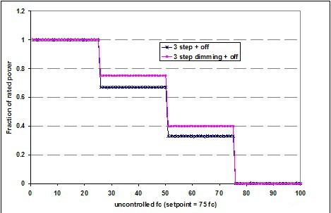
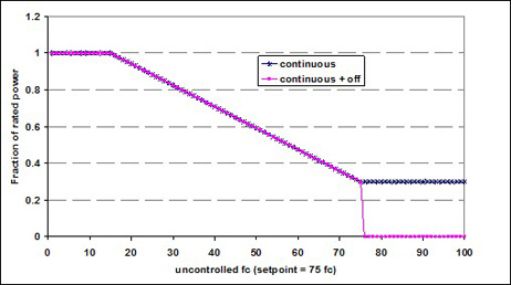
The type of control that is used to control the electric lighting in response to daylight available at the reference point. The options are as follows: · Stepped dimming controls have discrete steps of light output, but typically the intermediate steps of light output are associated with higher levels of fraction of rated power. When the lights are fully off or fully on, the fraction of rated power matches the fraction of light output. Stepped controls vary the electric input power and lighting output power in discrete, equally spaced steps. See Figure 4. · Continuous dimming controls have a fraction to rated power to fraction of rated output that is a linear interpolation of the minimum power fraction at the minimum dimming light fraction to rated power (power fraction = 1.0) at full light output. See Figure 5. · Continuous dimming + off controls are the same as continuous dimming controls except that these controls can turn all the way off when none of the controlled light output is needed. See Figure 5.
Figure 4. Example Stepped Daylight Control
Figure 5. Example Dimming Daylight Control |
| Units |
List (see above) |
| Input Restrictions |
As designed |
| Baseline Building | Not applicable |


| Minimum Diming Power Fraction | |
|---|---|
| Applicability | Spaces with daylighting controls |
| Definition |
The minimum power fraction when controlled lighting is fully dimmed. Minimum power fraction = (Minimum power) / (Full rated power). |
| Units |
Numeric: fraction |
| Input Restrictions |
As designed |
| Baseline Building | Not applicable |
| Minimum Diming Light Fraction | |
|---|---|
| Applicability | Spaces with daylighting controls |
| Definition |
Minimum light output of controlled lighting when fully dimmed. Minimum light fraction = (Minimum light output) / (Rated light output) |
| Units |
Numeric: fraction |
| Input Restrictions |
As designed |
| Baseline Building | Not applicable |
| Number of Control Steps | |
|---|---|
| Applicability | Daylighted spaces that use stepped controls |
| Definition |
Number of control steps. For step dimming, identifies number of steps that require fraction of rated light output and rated power fraction. |
| Units |
Numeric: integer |
| Input Restrictions |
As designed if stepped controls are provided in proposed building |
| Baseline Building | Not applicable |
This group of building descriptors is applicable for spaces that have daylighting controls.
| Daylight Modeling Method | |
| Applicability | All spaces with daylighting controls |
|---|---|
| Definition |
The method used to model daylighting. Daylighting credits must be calculated based on the local climate and daylight models of the space. Building descriptors are provided in this section for an internal daylighting model and two variations of an external daylighting model:
|
| Units | List (see above) |
| Input Restrictions | As designed |
| Lighting Schedules for Daylighting | |
| Applicability | Daylighted spaces that use the schedule adjustment method |
|---|---|
| Definition | A schedule that indicates the reduction in electric lighting for the lighting system that is being controlled. This schedule is applied to the lighting schedule (see above) to produce a schedule for lighting with daylighting controls. |
| Units | Data structure: schedule, fractional |
| Input Restrictions | The schedule of adjustments should account for seasonal variations in the time of day. Since the schedule will apply for both sunny days and overcast days, the adjustments should represent the conservative condition, e.g. the smallest savings. |
| Daylight Ratios | |
| Applicability | Daylighted spaces that use the daylight ratio method |
|---|---|
| Definition | A matrix of daylight factors for the space that represent the ratio on illumination at the daylighting reference point to the exterior illumination. The simulation engine calculates the daylighting illumination at the reference point based on this information and the exterior illumination and uses the daylighting control building descriptors to determine for each hour how the lighting power is reduced. |
| Units | Data structure: matrix |
| Input Restrictions | The special daylighting program used to calculate the daylight factors should use inputs consistent with those described below for the internal daylight model method. |
| Daylighted Area | |
| Applicability | All daylighted spaces |
|---|---|
| Definition | The floor area that is daylighted. Two types of daylighted areas are recognized. The primary daylighted area is the portion that is closest to the daylighting source and receives the most illumination. The secondary daylighted area is an area farther from the daylighting source, but still receives useful daylight. |
| Units | Data structure |
| Input Restrictions |
The default primary daylight area for sidelighting is a band near the window with a depth equal to the distance from the floor to the top of the window. The default secondary daylight area for sidelighting is a band beyond the primary daylighted area that extends a distance double the distance from the floor to the top of the window. Other daylight areas may be defined with appropriate documentation. The default primary daylight area for toplighting is a band around the skylight well that has a depth equal to the 70% of the ceiling height. The default secondary daylight area for toplighting is a band beyond the primary daylighted area that extends 140% of the ceiling height. Daylighted areas may not overlap or extend beyond partitions higher than 5 ft. Error checking includes ensuring that the following is true: Sidelit depth is less than or equal to ceiling height. Total daylit area is no greater than space area. |
| Reference Position for Illuminance Calculations | |
| Applicability | Daylighted spaces that use the internal daylight model method |
|---|---|
| Definition | The position of the daylight reference point within the daylighted space. Lighting controls are simulated so that the illuminance at the reference position is always above the illuminance setpoint. Thus for step switching controls, the combined daylight illuminance plus uncontrolled electric light illuminance at the reference position must be greater than the setpoint illuminance before the controlled stage of lighting can be tuned off. Similarly, dimming controls will be dimmed so that the combination of the daylight illuminance plus the controlled lighting illuminance is equal to the setpoint illuminance. |
| Units | Data structure |
| Input Restrictions | The reference location shall be as far away from daylight apertures as possible (but still within the daylighted area) so that all occupants have sufficient amounts of total illuminance (combined daylight and electric light) under all daylighting conditions. |
| Illuminance Setpoint | |
| Applicability | Daylighted spaces that use the internal daylight model method |
|---|---|
| Definition | The design illuminance for the daylighted space. The daylighting control adjusts the controlled lighting to maintain this level of illuminance at the reference point. |
| Units | Footcandles |
| Input Restrictions | As designed, but should be consistent with the visual tasks in the space and the recommendations of the IESNA. |
| Fraction of Controlled Lighting | |
| Applicability | Daylighted spaces that use the internal daylight model method or the daylight ratio method |
|---|---|
| Definition | The fraction of the lighting power in the daylighted space that is controlled by daylight. This is applicable when some of the luminaires in the space are controlled by daylighting and others are not. This input can be eliminated if multiple lighting systems are modeled for each space and the system that is controlled by daylight is separately specified. |
| Units | Numeric: fraction |
| Input Restrictions | As designed |
| Daylighting Control Type | |
| Applicability | Daylighted spaces that use the internal daylight model method or the daylight ratio method |
|---|---|
| Definition |
The type of control that is used to control the electric lighting in response to daylight available at the reference point. The options are:
[figure title="Example Stepped Daylighting Control" id="example-stepped-daylighting-control"] [figure title="Example Dimming Daylight Control" id="example-dimming-daylight-control"] |
| Units | List (see above) |
| Input Restrictions | As designed |
| Minimum Dimming Power Fraction | |
| Applicability | Daylighted spaces that use the internal daylight model method or the daylight ratio method and dimming controls |
|---|---|
| Definition | The minimum power fraction when controlled lighting is fully dimmed. Minimum power fraction = (Minimum power) / (Full rated power). See [bookref id="example-dimming-daylight-control"]. |
| Units | Numeric: fraction |
| Input Restrictions | As designed |
| Minimum Dimming Light Fraction | |
| Applicability | Daylighted spaces that use the internal daylight model method or the daylight ratio method and dimming controls |
|---|---|
| Definition | Minimum light output of controlled lighting when fully dimmed. Minimum light fraction = (Minimum light output) / (Rated light output). See [bookref id="example-dimming-daylight-control"]. |
| Units | Numeric: fraction |
| Input Restrictions | As designed |
| Number of Control Steps | |
| Applicability | Daylighted spaces that use the internal daylight model method or the daylight ratio method and stepped controls |
|---|---|
| Definition | Number of control steps. For step switching, this term defines even steps of light output and even steps of rated power fractions. For step dimming, identifies number of steps that require fraction of rated light output and rated power fraction. |
| Units | Numeric: integer |
| Input Restrictions | Integer less than 10. |
| Step Dimming Control Points | |
| Applicability | Daylighted spaces that use the internal daylight model method or the daylight ratio method and stepped dimming controls |
|---|---|
| Definition | Number of control steps. For step switching, this term defines even steps of light output and even steps of rated power fractions. For step dimming, identifies number of steps that require fraction of rated light output and rated power fraction. |
| Units | Data structure. Matched pairs of data (light output and fraction of rated power) for the defined number of control steps |
| Input Restrictions | Integer less than 10. More than 10 steps approximate with continuous dimming. |