This group of building descriptors applies to proposed design systems that vary the volume of air at the zone level. The building descriptors are applicable for baseline building systems 5 through 8.
|
Design Airflow |
|
|---|---|
|
Applicability |
Systems that vary the volume of air at the zone level |
|
Definition |
The air delivery rate at design conditions |
|
Units |
cfm |
|
Input Restrictions |
As designed. If the unmet load hours in the proposed design are greater than 300, the building descriptor may need to be modified to meet the criterion. The simulation for compliance purposes shall not proceed if the unmet load hours are greater than 300. |
|
Baseline Rules |
For systems 5 through 8, the software shall automatically size the airflow to meet the baseline building loads based on the greater of the following approaches:
However, airflows for systems serving laboratory spaces shall be sized based on a suppluy air to room air temperature difference of 17 °F or the required ventilation air or makeup air, whichever is greater. |
|
Terminal Minimum Stop |
|
|---|---|
|
Applicability |
Systems that vary the volume of air at the zone level |
|
Definition |
The minimum airflow that will be delivered by a terminal unit before reheating occurs |
|
Units |
Unitless fraction airflow (cfm) or specific airflow (cfm/ft²) |
|
Input Restrictions |
This input must be greater than or equal to the outside air ventilation rate. |
|
Baseline Rules |
For systems 5 through 8, the minimum airflow for the VAV boxes should be 30% of zone the peak supply air volume; the outside air ventilation rate; or the air flow rate required to comply with applicable codes or accreditation standards, whichever is larger. Refer to section ‘Zone Exhaust’ for requirements related to systems serving laboratory spaces. |
|
Terminal Heating Control Type |
|
|---|---|
|
Applicability |
VAV boxes with reheat |
|
Definition |
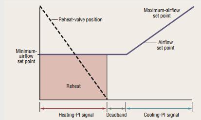
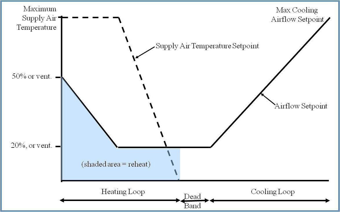
The control strategy for the heating mode. Single Maximum. In the single maximum control mode, the airflow is set to a minimum constant value in both the deadband and heating mode. This airflow can vary but is typically 30 to 50 percent of maximum. This control mode typically has a higher minimum airflow than the minimum used in the dual maximum below, resulting in more frequent reheat. Figure 3.6.5-1 Single Maximum Control SequenceCourtesy: Taylor Engineering Dual Maximum. This control sequence raises the SAT as the first stage of heating, and increases the airflow to the zone as the second stage of heating. 1. The first stage of heating consists of modulating the zone supply air temperature setpoint up to a maximum setpoint no larger than 95ºF while the airflow is maintained at the dead band flow rate. 2. The second stage of heating consists of modulating the airflow rate from the dead band flow rate up to the heating maximum flow rate (50% of design flow rate) while maintaining the maximum setpoint temperature. Figure 3.6.5-2: Dual Maximum Control SequenceCourtesy: Taylor Engineering |
|
Units |
List either Single Maximum or Dual Maximum (see above) |
|
Input Restrictions |
As designed |
|
Baseline Rules |
Single Maximum at 30% of zone peak air flow or the outside air ventilation rate, or the air flow rate required to comply with applicable codes or accreditation standards, whichever is larger. Refer to the section ‘Zone Exhaust’ for requirements related to laboratory spaces. |